blogTech

Integrated Waveform Explained: Satcom IW

An integrated waveform refers to a graphical representation that combines multiple waveforms into a single display. It allows for the simultaneous observation and analysis of different waveforms, such as audio signals or electronic waveforms, within a single visual representation. This can be useful for comparing waveforms, identifying correlations or patterns, and gaining a comprehensive understanding of the signals being analyzed.


Integrated Waveform: The Joint UHF MILSATCOM Technical Working Group (TWG)


The Joint UHF MILSATCOM Technical Working Group (TWG) is actively working on the development of a single integrated waveform to enhance the existing demand-assigned multiple access (DAMA) waveforms. This paper outlines the key features and benefits of the forthcoming waveform and provides several suggestions for further improvement. The proposed enhancements include an alternative data structure for control channel order wire bursts, protocol enhancements to address slot-conflict issues in half-duplex terminals, support for operation across multiple satellites in the same coverage area, improved satellite range determination methods, and reduced network overhead through the inclusion of terminal status in ranging bursts. The integrated waveform builds upon the concept of the slave channel from MIL-STD-188-183A, enabling the transmission of forward order wire (FOW) bursts on selected control channels while allowing user communication on any available satellite channel.


The Viasat UHF DAMA/IW Network Management Solution (NMS)

The Viasat UHF DAMA/IW Network Management Solution (NMS) enables concurrent communications between UHF SATCOM terminals and networks, utilizing MIL-STD Time-Division Multiple-Access (TDMA) protocols.

The Viasat NMS consists of:
  • Viasat Visual Integrated SATCOM Information, Operation, and Networking (VISION) planning and network management software
  • Viasat Integrated Waveform Channel Controller (IWCC)
  • Viasat Network Channel Controller (VNCC)
  • Viasat Network Terminal Controller (VNTC)

Integrated Waveform Design Based on UAV MIMO Joint Radar Communication

The problem of constructing orthogonal waveforms for integration in Multiple Input/Multiple Output (MIMO) radar and communication systems presents a significant challenge. In the context of MIMO antenna scenarios, a solution is proposed using a sub-LFM-BPSK waveform combined with a chaotic spread spectrum code. This design enables each MIMO antenna to transmit unique communication data after spread spectrum processing, facilitating omnidirectional detection in MIMO applications. Closed-form expressions for the integrated orthogonal waveform, subject to specific constraints, are derived to further enhance the understanding and implementation of the proposed solution.

integrated waveform explained

1. Introduction

With the rapid development of 5G communication technology, the proliferation of wireless devices has led to increasing conflicts and interference between wireless communication and radar systems. To address this issue, multiple-input/multiple-output (MIMO) antenna technology has gained popularity in the communication field, extending its application to unmanned aerial vehicles (UAVs). In parallel, MIMO radar technology has emerged, offering enhanced radar detection capabilities through improved narrow beamforming and increased freedom compared to single-antenna radar systems.

The coexistence of MIMO communication and MIMO radar has evolved from spectrum sharing to complete integration, enabling the design of waveforms specifically tailored for MIMO antennas. Previous research efforts have primarily focused on integrated waveform design for single antennas, resulting in notable achievements. For instance, researchers have proposed the integration of linear frequency modulation (LFM) radar signals with minimum shift keying (MSK) communication, analyzing the characteristics of the integrated signal. They have also explored time-frequency characteristics and devised strategies to ensure high-throughput data transmission in non-dispersive spectra.

To distinguish between radar and communication signals, an Oppermann multiphase sequence spread spectrum code has been introduced. Additionally, the design of an integrated waveform combining LFM with continuous phase modulation (CPM) has been proposed, with an analysis of its ambiguous function and the use of data reconstruction techniques to enhance spectrum performance. The integration of radar and communication based on orthogonal frequency-division multiplexing (OFDM) has also been extensively studied, providing comprehensive design guidelines and performance analyses.

These advancements in integrated waveform design for MIMO antennas and the integration of radar and communication systems pave the way for improved coexistence and functionality in the dynamic landscape of wireless communication and radar technology.

Upon analyzing the existing single-antenna integrated waveform schemes and MIMO radar communication integration approaches, several problems can be identified:

  • The focus of current MIMO integrated systems is primarily on formalizing beam direction design, while the specific expression of the integrated waveform is often overlooked. This lack of consideration for waveform universality hinders its broader application in radar communication integration.
  • Some studies simplify the analysis process by considering the communication signal with constellation distribution as the integrated waveform. While this facilitates communication performance analysis, it fails to comprehensively account for radar application scenarios and may not optimize performance accordingly.
  • Although single-antenna integrated waveform design technology is well-established, difficulties arise when attempting to ensure that each antenna in a MIMO radar communication integration system transmits an orthogonal waveform for constructing omnidirectional detection signals. The challenge of achieving orthogonal waveforms limits the practical application of integrated MIMO waveform design.

Addressing these issues will be crucial in advancing the field of MIMO radar communication integration and optimizing the performance and applicability of integrated waveform designs.

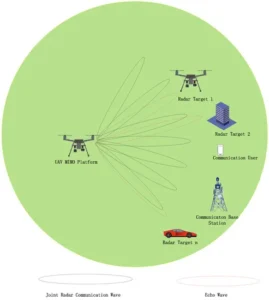
This paper addresses the aforementioned problems by proposing an integrated omnidirectional orthogonal waveform method for MIMO radar communication in UAV scenarios. The application scenario diagram is depicted in Figure 1.

integrated waveform

This paper makes the following contributions:

(1) Building upon the integrated waveform concept of a single antenna, the paper constructs an integrated orthogonal waveform set for MIMO scenarios by utilizing the orthogonal spreading code technique.

(2) The paper analyzes the radar detection performance and communication performance of the orthogonal waveforms in the integrated MIMO system within the UAV scenario. Mathematical expressions are derived to describe these performance metrics.

(3) Simulation experiments are conducted to evaluate the performance of the orthogonal waveforms. The results validate that the integrated system exhibits superior radar and communication performance.

The integration of radar and communication systems offers mutual benefits and holds great potential for various future applications. In the context of vehicles-to-vehicle scenarios, the joint radar communication system plays a crucial role in environment recognition, vehicle position tracking, speed monitoring, and detecting abnormal events on the road. Real-time monitoring of traffic flow using the integrated radar communication system enables efficient coordination of people, vehicles, and road infrastructure, ensuring traffic safety and enhancing the overall operational efficiency of the transportation system.

In the domain of smart homes, the integration of radar and communication technology enables the use of Wi-Fi signals to detect human movements and behaviors. This information can be leveraged by smart home systems to provide advanced functionalities and enhance the overall user experience. Source: https://www.mdpi.com/2078-2489/14/8/455

The structure of this paper is organized as follows:

  • The first part addresses the challenging problem of constructing an orthogonal waveform set in the MIMO UAV scenario.
  • The second part presents the proposed model for orthogonal integrated waveforms specifically designed for UAV scenarios.
  • The third part analyzes the radar performance and communication performance of the integrated waveform system.
  • The fourth part validates the performance of the MIMO waveform through experimental simulations, including the evaluation of ambiguity function, azimuth-range mapping, and spectral characteristics.

The integrated waveform, a proposed improvement to the UHF SATCOM DAMA standards

The Joint UHF MILSATCOM Technical Working Group (TWG) is currently working on the development of a single integrated waveform that aims to provide a significant improvement over the existing demand-assigned multiple access (DAMA) waveforms. This paper highlights the key features and benefits of the waveform being developed and puts forward several suggestions for enhancing the waveform, which the authors believe should be considered by the TWG.

The suggested improvements encompass various aspects of the waveform. Firstly, an alternative approach to the data structures for control channel orderwire bursts is proposed. Additionally, protocol enhancements are recommended to address slot-conflict issues for half-duplex terminals and enable operation across multiple satellites in the same coverage area. The paper also suggests more effective methods for satellite range determination and reducing network overhead by incorporating terminal status within ranging bursts sent by terminals.

The integrated waveform (IW) builds upon the slave channel concept introduced by MIL-STD-188-183A. It achieves this by transmitting forward orderwire (FOW) bursts on selected control channels, while user communication can be allocated to any available satellite channel. By eliminating the predefined time-slot frame formats used in MIL-STD-188-183 and leveraging the multi-h continuous phase modulation (CPM) developed for MIL-STD-188-181B, the IW has the potential to more than double the number of circuits that the existing satellite constellation can support.


Improving satellite bandwidth utilization by applying combinatorial optimization to the Integrated Waveform (DAMA UHF SATCOM)

The integrated waveform, known as DAMA UHF SATCOM, is defined in MIL-STD-188-181C/182B/183B/185A. Its purpose is to enhance satellite bandwidth utilization compared to legacy SATCOM waveforms by implementing a TDMA communication system.

One of the limitations of the previous version, MIL-STD-188-183A, was the static definition of user communication (UCOM) services. To address this, MIL-STD-188-183B introduced increased flexibility in assigning services within a frame. However, this flexibility resulted in a higher likelihood of fragmented service layouts both within channels and across channels as terminals requested the allocation, relocation, and deallocation of UCOM services.

To mitigate this fragmentation issue, the integrated waveform incorporates an innovative service update feature. This feature allows the network management system (NMS) of the integrated waveform to defragment the service layout across all satellite channels under its control. By doing so, the NMS can create larger contiguous regions of unallocated channel space, which can then be utilized to accommodate current and future service allocation requests.


Reducing terminal slot contention by applying set theory to the integrated waveform (DAMA UHF SATCOM)

The Integrated Waveform (DAMA UHF SATCOM), as defined in MIL-STD-188-181C/182B/183B/185A, is designed to enhance satellite bandwidth utilization compared to conventional SATCOM waveforms through the use of a TDMA communication system.

To address the limitations of statically defined user communications (UCOM) services in MIL-STD-188-183A, MIL-STD-188-183B introduced the flexibility to assign services almost anywhere within a frame. While this flexibility has the potential to greatly improve bandwidth utilization, it can be limited by terminal slot contention, particularly for half-duplex terminals. The benefits of the flexible service assignment feature may be diminished as a result.

However, the IW Network Management System can mitigate the impact of terminal slot contention by efficiently allocating and relocating Downlink and Uplink support services. By strategically assigning UCOM services wherever necessary, the system can achieve optimal satellite channel utilization while minimizing the performance impact due to slot contention.

This paper focuses on the application of set theory to the allocation of Downlink and Uplink support services within a TDMA communications system. By leveraging set theory principles, the aim is to reduce the impact of slot contention and improve the overall utilization of satellite bandwidth.


Multiple layered method of terminal slot contention resolution for the Integrated Waveform (DAMA UHF SATCOM)

The Integrated Waveform, specified in MIL-STD-188-181C/182B/183B/185A, implements a TDMA communication system to improve satellite bandwidth utilization compared to conventional SATCOM waveforms.

To address the limitations of statically defined user communications (UCOM) services in MIL-STD-188-183A, MIL-STD-188-183B introduced the flexibility to assign services anywhere within a frame. While this flexibility can enhance satellite bandwidth utilization, it also introduces complexities related to slot contention.

To mitigate the increase in slot contention, the IW Network Management System employs a technique that allows the allocation of multiple Uplink and Downlink support services. This approach accommodates the diverse placements of UCOM services. However, a downside of this technique is that it transfers the responsibility of detecting and resolving slot contention between the desired UCOM services and the services crucial for Uplink and Downlink acquisition to the terminal systems.

Method of estimating the link quality of a UHF SATCOM channel

This paper discusses the utilization of fast Fourier transforms (FFTs) to determine MILSATCOM channel quality. By using FFTs, the system can improve its ability to select the optimal over-the-air modem and provide users with the means to manually locate geostationary satellites for improved antenna placement.

The use of directional antennas in geostationary satellite communications requires precise antenna positioning for optimal signal quality. The Integrated Waveform includes requirements for measuring C/No and utilizing fast Fourier transforms to improve channel quality determination. These techniques can assist in selecting the appropriate over-the-air modem and provide users with guidance on antenna placement for improved communications performance.


A method is proposed for allocating multiple asynchronous data transfer (ADT) services by utilizing the remaining TDMA channel space to accommodate high throughput service requests.

As the satellite communication network becomes heavily loaded, allocating large timeslots for high-throughput data services becomes challenging. To overcome this, the unique characteristics of ADT services allow terminals to utilize multiple smaller timeslots to achieve the same throughput as a single larger timeslot.

This paper presents a method to further improve satellite resource utilization by allocating one or more timeslots, which consist of the remaining space in a satellite channel after allocating all other services, to terminals that require high throughput ADT services.


Estimating link quality in a time-slotted UHF SATCOM system using a proposed method.

When using geosynchronous satellites in tactical radio communications, knowing the precise location of the satellite is crucial due to the use of directional antennas. Conducting a received signal strength indication (RSSI) check is beneficial to ensure correct channel configuration and optimal antenna pointing. Typically, this measurement involves transmitting a known signal on the uplink frequency and receiving the retransmitted signal on the downlink frequency.

This paper presents an alternative method that utilizes multiple orthogonal single-frequency tones throughout the transmission duration, replacing a single contiguous transmission. By employing a payload consisting of a single frequency, the paper also discusses an RSSI check method that accommodates the small timeslots in systems like the Integrated Waveform.


Communication analysis of integrated waveform based on LFM and MSK

The Integrated Waveform has significant impacts on both radar and communication systems. In terms of communication, two key aspects are analyzed: the limitation of modulated data and the bit error rate.

To analyze the limit of modulated data, a time-frequency analysis method is employed. Through complex deduction, it is found that the bandwidth of the integrated waveform can extend if the codes are not properly designed. However, with well-designed codes, the bandwidth remains within reasonable limits.

The bit error rate of the integrated waveform is deduced in detail, taking into account matched filtering. It is determined that the bit error rate of the integrated waveform is equivalent to that of Minimum Shift Keying (MSK). This conclusion is further supported by simulation results. Source: https://ieeexplore.ieee.org/document/7455239/keywords#keywords


Integrated Waveform Design for Centralized MIMO-OFDM-BPSK-LFM Radar Communication

The autocorrelation function of a Binary Phase Shift Keying (BPSK) modulation, with signal amplitudes of ±1, exhibits a peak-like shape. In BPSK-Linear Frequency Modulation (LFM), the fuzzy function is formed by multiplying two parts. The left part represents the fuzzy function of the standard LFM signal, while the right part is the autocorrelation function of the BPSK communication symbol, which remains unchanged with random symbol variations. Consequently, the fuzzy function performance of BPSK-LFM is superior to that of LFM. However, the communication transmission rate of BPSK-LFM is lower.

In QPSK-LFM and 8PSK-LFM modulations, the shape of the fuzzy function changes with the random communication symbol variations. On the other hand, Orthogonal Frequency Division Multiplexing (OFDM) multi-carrier modulation can enhance spectrum efficiency and communication transmission rate. Additionally, Multiple Input Multiple Output (MIMO) technologies can increase channel capacity and spectrum efficiency without increasing signal bandwidth.

Considering these factors, this paper proposes a centralized MIMO-OFDM-BPSK-LFM signal for the integrated radar communication system. Centralized MIMO radars have closely positioned receiving and transmitting antennas, facilitating their placement together.


Integrated Waveform and Intelligence (IWAI): Physical Layer Solutions to Sustainable 6G

Integrated Waveform

The deployment of communication networks, particularly with the advent of 5G and the anticipated future of 6G, has brought attention to the significant power consumption associated with these systems. It is estimated that information and communications technology (ICT) contributes 1.8%-2.8% of carbon emissions. The denser placement of base stations in 5G systems has resulted in higher power consumption compared to 4G. Furthermore, studies suggest that a potential 6G system could consume nearly 50 times more power than a 5G system due to factors such as increased antenna count, wider spectral bandwidth usage, and denser base station deployments.

With the global priority of improving energy efficiency and achieving net-zero sustainability, various industries and research institutes are actively pursuing sustainable technologies to reduce energy usage and carbon emissions. The aim is to reshape the physical layer techniques in 6G to lead the way in sustainability innovations for future communications. The UK government’s Wireless Infrastructure Strategy: A Vision for 2030 recognizes the importance of sustainable communication systems in its net-zero objectives and has made it a top priority.

While hardware upgrades through advanced manufacturing can contribute to reducing power consumption, this approach has limitations in 6G systems where more base stations are required to cover a given area. Therefore, achieving net-zero goals in 6G necessitates a fundamental breakthrough in energy-efficient physical signal design, specifically waveform design. By focusing on improving the efficiency of physical signals, significant progress can be made in reducing power consumption and achieving sustainable communication systems in 6G.

What is Satcom IW?

The SATCOM Integrated Waveform (IW) is a technology that improves the efficiency of satellite communication by utilizing Time Division Multiple Access (TDMA). It replaces the older Demand Assigned Multiple Access (DAMA) SATCOM system and offers a more flexible waveform structure. SATCOM IW allows for tailored communication accesses based on operational requirements, enabling more effective and optimized satellite channel utilization.

Integrator and differentiator waveforms

Integrator and differentiator waveforms are specific types of waveforms used in signal processing and electrical engineering.

An integrator waveform is characterized by an output that is proportional to the integral of the input waveform. It effectively sums up the input values over time, resulting in an output waveform that emphasizes low-frequency components and attenuates high-frequency components. Integrators are commonly used in applications such as audio processing, filtering, and control systems.

On the other hand, a differentiator waveform produces an output that is proportional to the derivative of the input waveform. It emphasizes high-frequency components and attenuates low-frequency components. Differentiators are often used in applications such as edge detection, signal differentiation, and frequency analysis.

Both integrator and differentiator waveforms are valuable tools in signal processing and can be employed in various applications depending on the specific requirements and goals of the system.

Integrator amplifier waveform

An integrator amplifier is an electronic circuit that produces an output waveform that is proportional to the integral of the input waveform. It is commonly used in analog signal processing applications.

In an integrator amplifier circuit, the input signal is connected to the input terminal of an operational amplifier (op-amp) through a resistor. The output of the op-amp is then fed back to the input terminal through a capacitor. The resistor and capacitor form a time constant, which determines the rate at which the input signal is integrated.

When a time-varying input signal is applied to the integrator amplifier, the capacitor charges or discharges according to the integral of the input waveform. As a result, the output waveform of the integrator amplifier is a voltage signal that represents the integrated value of the input signal over time.

Integrator amplifiers are commonly used in applications such as analog filters, audio processing, waveform generation, and control systems. They play a crucial role in various electronic systems that require the integration of input signals for specific purposes.


Read More:

Related Articles

Leave a Reply

Your email address will not be published. Required fields are marked *

Back to top button